Manfred's TR1. Discussion Boards
https://www.tr1.de/cgi-bin/yabb2/YaBB.pl

TR1 Discussion Boards >> Tips, tricks and solutions for the TR1 >> Too long in pieces. TR1 ignition system
https://www.tr1.de/cgi-bin/yabb2/YaBB.pl?num=1397831565

Message started by JohnB on 18.04.14 at 16:32:45

Title: Too long in pieces. TR1 ignition system
Post by JohnB on 18.04.14 at 16:32:45

and too long away from here...  only when I sit down and calculate, I realise it is NINE years since my TR1 was last in one piece and being ridden.

In the interim, I find the carburretors are full of crap, and the ignition is dead...

I recommend http://www.nrp-carbs.co.uk/ for the carb rebuild kits

I recommend http://www.ignitech.cz/en/ for the ignition bits

I bought two coils and a TCI from ignitech, but still no spark, as I dreaded, the pick ups must be at fault.

Note, I previously checked them, and found 166 Ohms on each, which is according to the Haynes manual within spec, yet, no spark

Crank on starter motor with pickup outputs on to oscilloscope and does not quite make one division with scope set to 0.2 V per div....

At this time I do not know either what the output at cranking speed SHOULD be, or the minimum trigger voltage for the Ignitech TCI unit, either way, I am convinced it is currently way too low....

So, time to pull the left side cover...

Pics here

http://exeter-computer-repair.co.uk/tr1/

It looks like an original yam part, with the pickups bonded to the carrier plate, so as I type checking with ignitech which of their pick ups to get, and looks like I'll have to modify the carrier.

I'm determined the bitch is going to live again...lol


Title: Re: Too long in pieces.
Post by JohnB on 18.04.14 at 16:51:40

Just heard from Ignitech, the TC1 unit needs at least 0.7 Volts at cranking speed to work....  so I was getting 30% of that...lol


Title: Re: Too long in pieces. TR1 ignition system
Post by JohnB on 22.04.14 at 11:33:27

OK..

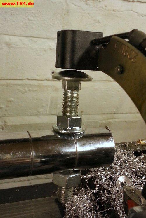
After much looking around, I find the pick-up coils (induction type) are on a bracket, made by Mitsubishi electric for Yamaha.

You can see the part in the attached photo.

No markings on the front, on the rear it says "F7T503" and Mitsubishi mark and then "71"

After research, I find it is available from Yamaha Japan.

Part number 4x7 81670 20(00)

Price in UK Pounds is £219 + vat = £263.21

-------------------------------------------------

Now, many options, I can try to rebuild existing ones with new pickups from ignitech, maybe 75 euros, or, now I have part numbers, I can try to find someone somewhere with "new old stock" maybe 150 euros, or, I can buy this part, factory direct, warranty... and after all is going inside the engine, and crucial part for well running of the engine, so I sit in car park for 5 minutes having a smoke and think assholes, buy original part direct from Yamaha.

ETA from Japan mid May.

So, when it comes will fit it, and take accurate readings of coil resistance from new, AND take correct AC voltage readings at cranking speed, and picture of oscilloscope trace...

Because this is half the battle to me.

I know from Ignitech TCI unit requires 0.7 V to trigger.

I know from Haynes book of lies pick up coils are supposed to be 124-186 Ohms, mine were 166.

I do not know what voltage pick up coils are supposed to generate at cranking speed, at tickover, or at a couple of thousand RPM...

So to me only way to get this right is to buy factory new, and measure.

Watch this space.


Title: Re: Too long in pieces. TR1 ignition system
Post by JohnB on 22.04.14 at 13:44:38

Meh, just had a phone call from the dealer, bring the reciept back in for a refund.

They have spoken to Yamaha Japan.

1/ The last one in stock has already gone, I missed it by one day.

2/ They now have no stock.

3/ They will not be getting any new stock... it is end of life.

watch this space.


Title: Re: Too long in pieces. TR1 ignition system
Post by JohnB on 22.04.14 at 14:29:42

Since I must now do this the hard way... document the process here.

1/ Because the TR1 has the pickups on the outer cover with the alternator stator windings, you can't manually adjust the gap clearance, which is why Mr Yamaha designed it the way he did, with the now unobtainable part, which allowed no adjustments.

Measuring the gap between the stator windings and the pickups, and then measuring the thickness of the rotor, it is clear Mr Yamaha did this right, there is just about 1mm clearance for the rotor, in total, so approx 0.5 mm either side, stator <> rotor, and rotor <> pickups.

This all means that buying new pickups from ignitech
http://www.ignitech.cz/en/vyrobky/accessories/pick-up/pick-up.htm
I have to be EXTREMELY careful of dimensions...
http://www.ignitech.cz/en/vyrobky/accessories/pick-up/pickup%20dimension.jpg

If I look at mine, since the metal mounting bar is fixed, it is selecting the correct dimension pickups, and then mounting them accurately, that is the trick.

Some pictures.
http://exeter-computer-repair.co.uk/tr1/index.php?folder=VENJLXBpY2t1cHM=

Thickness of picups side to side, along arc of rotation of crankshaft, 19.2 mm
height of pickups, top to bottom, along line of radius from crankshaft, 21.0 mm
Depth of pickups, along axis of crankshaft, 22.67 mm - note this is sat on top of mounting plate.
Mounting plate is 2.0 mm

The important numbers

From centre of pickup to inner side of plate / bottom of pickup body where it sits on plate 11.0 mm

Hear from Ignitech that from the pickups listed on their page, any of them will work with their TCI, resistance numbers not important.

So...

1/ height of centre of pickup sensor from lower side of plate, 11.0 mm, this is crucial number, this is measurement B on ignitech data sheet

2/ must be enough space to actually fit mounting screws on plate, this is measurement C on ignitech data sheet

3/ thanks to yamaha design, measurement A on ignitech data sheet not significant, we have room for them all

Only way to mount pickups with measurement B greater than 11mm is to modify metal carrier plate, possibly significantly weakening it.

So P1, P2, P4, P6, P7, P8, P11, P20 & P21 all too "high"

This leaves P3, P5, P13 & P22

P3 has a dimension C of 9mm, is flat base, and 250 ohm

P3 dimension B is 6mm, we need 11,  so need to add 5.0 mm shim

should be good to go...

watch this space....


Title: Re: Too long in pieces. TR1 ignition system
Post by JohnB on 22.04.14 at 14:45:14

Also, before I forget... note the detail in following pic of original yamaha part...

not enough room for standard pickup mounting bracket, so we will have to modify this...

next step, make a jig for original fitting so we can be sure replacement is perfect.


Title: Re: Too long in pieces. TR1 ignition system
Post by stefan stein on 22.04.14 at 15:22:01


Hello,

You are obviously much more into this electronic business than me. But I still doubt that the pickpus should be rotten. They are frequently and falsely suspected, rarely to blame, when there is no proper ignition. Why should they have gone bad, when they did a good job before?

Regards,

Stefan


Title: Re: Too long in pieces. TR1 ignition system
Post by JohnB on 22.04.14 at 15:43:36

The bike has been in pieces for 9 years.

It ran fine at the time, but I have no way of knowing how much better than the minimum required they were at that time, I do know they are 33 years old, and I do know that inductive pickups do fade with time in every other automotive application I have seen.

As I type... I have...

New spark plugs
New coils and HT leads from Ignitech
New TCI from Ignitech
New Yuasa battery

Literally the only remaining component of the ignition system is the pickups.

I was getting no spark of any kind, not even with plugs outside engine and earthed to engine.

I did measure voltage being output by pickups at cranking speed, it was below 50% of the required voltage (0.7 v) to trigger ignitech unit, and also far lower than any inductuion pick up I know of, for example ever early GM ones in automobiles would range from 0.6 volt at slow cranking to 22 volt at max RPM.

It is a process of elimination.


Title: Re: Too long in pieces. TR1 ignition system
Post by JohnB on 22.04.14 at 16:45:51


*very* rough beginning to jig

needs to first be made so that ignition pick up units and carrier plate can be removed from jig and replaced as often as you like, but can only ever be in one place, no movement, so far just the two carrier holes...

Note, in the bike, these are 6mm coarse thread, not normal.

then you can see from the matchbox and pop rivet the idea, make up blocks with a centre piece that EXACTLY lines up with the centres of the pick ups on the original equipment.

Then when removing these pickups and fitting the new ones from ignitech, it is simple to get placing, gap, and everything else correct to better than 0.1 mm.
no guesswork.


Title: Re: Too long in pieces. TR1 ignition system
Post by JohnB on 22.04.14 at 21:06:14

You see, Stefan Stein's reply made me think...

1/ yes, nobody wants to think these things die

2/ there is no real way to test them except on a running bike, so use gaskets, oil, every time you change..

Always there is a inverse connection between how difficult it is to get at a thing, how awkward it is, etc, and how prepared people are to accept that thing is defective....  TCI unit, no problem, pop the tank off, job done...

So I sit, drink coffee, smoke, think....

In engine pickups are triggered by non magnetic steel "step" just 10 mm high....

I can simulate this by spinning a steel bolt in the lathe, and use feed screws to position pickup very very close to bolt.

OK, not a perfect experiment, perfect experiment is pull rotor and spin this on lathe, but this is good enough experiment, 8mm coach bolt not as chunky as the step in the rotor, but not a million miles away, and I can set gap down to 0.1 mm, which will make up for this to some extent.

You can see from photo at rest, this should work.

You can see 80 second video of this experiment here

deleted link

warning is 350 MB so I will not leave it up forever...


Edited, smaller version...
http://exeter-computer-repair.co.uk/tr1/TCI-pickups/test.mp4
23 MB only...


So variable speed drive in lathe, pickup set to 0.1/0.2 mm from 8mm dia coach bolt (nice radius head) and multimeter connected and set to AC Volts scale, turn the dial and spin her up slowly

Maximum reading on multimeter is 0.3 VAC.. yes, digital multimeter not most accurate thing on planet, but, I have done this before with digital multimeter and oscilloscope, digital multimeter is not that far out, not so far it is "wrong"

http://exeter-computer-repair.co.uk/tr1/TCI-pickups/00000-mts_snapshot_01-23_2014-04-18_19-33-59.jpg

Digital multimeter and oscilloscope agree within a few %

A few % on a reading of 0.3 VAC is nothing, when TCI requires MINIMUM of 0.7 VAC to trigger.

=================================================

In automotive applications we used to find over time the cores of pickups became too magnetic, car ones used to be made with soft iron core and a small magnet at end, and eventually iron core became magnetised, which reduced output voltage... you could partially fix by demagnetising, but never proper cure.

I'll say again, problem is, I do not have numbers for the voltage the pickups should generate at cranking speed, and at tick-over speed, and at say 3,000 RPM... if I could have bought new item, I could measure.

As far as I know, nobody has this data for TR1 specifically... everyone has 20 to 30 year old units they can measure, not factory fresh.

-----------------------------------

So again, not a perfect test, because I use a bolt and not spinning the rotor in the lathe, nevertheless, I GET THE SAME VOLTAGE as when on bike and cranking with starter, so not a million miles out, it is I think a valid test.

33 year old ignition pickups = crap.


Title: Re: Too long in pieces. TR1 ignition system
Post by JohnB on 30.04.14 at 18:09:45

Meh.. did a long post and lost it....


Basically been doing more measuring....

see new pics at http://exeter-computer-repair.co.uk/tr1/index.php?folder=VENJLXBpY2t1cHM=

5.9 + (8.73/2) = 10.26

39.83 - 10.26 = 29.57 mm

29.57 is distance from face to centre of pickup iron in rotor.... pics show rotor to face distance as 42 but this is incorrect, one hand for camera, one for vernier, not able to measure in correct method or place, 39.83 is a closer to correct number

=======================================

25.0 - 2.88 = 22.12 this is measurement from face on outer case to where pickup carrier plate sits... 2.88 is thickness of vernier used for straight edge.

In previous post I say centre of pickup is 11 mm from mounting plate.

22.12 + 11.0 = 31.12

Centre of pickup iron on rotor is out ----> from face of inner casing by 29.57 mm

Centre of pickup sensor on stator is out ------> from face of outer casing by 31.12 mm

31.12 - 29.57 = 1.55 mm

Note the two underlined bits above, between these two casings there must be a gasket.. this will INCREASE this number... 0.5 mm gasket + 1.55 mm = 2 mm out....

And also this is the "wrong" direction if I am going to be replacing original pickup sensors, with "B" height of 11 mm with ignitech ones with a "B" height of 14 mm.

At this time, I'm not convinced of the accuracy of my measurements either, sure, they are close, but I am giving numbers with 2 digit precision, 0.01 mm, no way my measurements were that good, too quick and dirty.

My thinking is Mr Yamaha got the centre of the iron slug on the rotor, and the centre of the pickup sensor, to within plus or minus 0.1 mm.

I need to clean up and measure properly, eg get REPEATABLE measurements for these things, I think the current 1.55 mm "error" will disappear, but I *need* these accurate numbers, because as we see, there is no point doing this unless we do it to a professional standard, and these motors are unusual in that the pickups positioning is not adjustable.

Two vital points.

1/ I need to do this in a workmanlike way and measure and document everything, because *if* it works but is not quite right, I am no longer able to go back to the starting point... once you modify something you cannot measure what size it b*used* to be...

2/ I, or someone else, may (will) want to repeat this, and get it right first time, and have faith in the other guy's measurements...  :o


Title: Re: Too long in pieces. TR1 ignition system
Post by JohnB on 30.04.14 at 20:47:51

I should also make it clear that what I am doing at the moment is working on generating a 3D CAD drawing of the respective parts, simplified somewhat, but with all the relevant dimensions and clearances and angles etc sorted...

Just need a couple or four hours free to put the whole lot on the mill table and measure with the laser and DRO, that way I will get exact centres and dimensions and radius etc etc


Title: Re: Too long in pieces. TR1 ignition system
Post by JohnB on 01.05.14 at 12:43:37

OK, so we start to make some progress, no work this morning so was able to go out to workshop and put outer cover on the mill and fire up DRO and take some measurements.

DRO is a glass scale 3 axis job accurate to 5 microns 0.005 mm, of course only using X and Y scale for these measurements.

Visual positioning from a red dot laser centre finder, as always a camera flares the laser and makes it look a lot less precise than it is, particularly with edge finding, 25 microns (0.001 inch) movement creates a very visible difference in the beam.

If you know the co-ordinates of three points, you can accurately plot the exact circle that they lie on, for this and the rest of the simple CAD work I will be using the excellent Rhino package.

I first found three points on the inner radius of the stator, and used these to calculate the centre. X=0, Y=0

A random selection of the 25 other points measured was re-verified after going back to 0,0, they were all within 25 microns.

I say all this here because it is important to understand the methodology before you can have any faith in the numbers generated.

Meaningful accuracy in the real world of 0.1 mm is good enough, certainly when it comes to machining or fabrication for stuff like this you do not need to work to the same accuracy as grinding a crankshaft journal, but these base measurements are all "good enough" at 25 micron or 0.025 mm or 0.001 inch accuracy, certainly the alloy casing will expand and contract this much going from ambient temp on my mill of 16 degrees to operating temperature in a hot running engine...

Accurate measurements as a starting point are GOOD, but we do not need to be anal in carrying the same level of accuracy forwards through the process.

Off to Rhino....


Title: Re: Too long in pieces. TR1 ignition system
Post by ernie8 on 01.05.14 at 13:38:40

Hi John,
Sorry, but I believe you are thinking into the wrong direction. In principle I agree with Stefan, I don't believe that the pick ups are rotten.
You have listed up all components you have checked, but that's not all: did you check all wiring Connections, all cables for breakes and good contacts, from the pick ups to TCI and up to the handle bar? Did you check the emergency Switch?
I have never heard, that the pick ups failed, and why for hell should both of them fail at the same time? From my view this is an extremely low probability. When I see on your pics your engine cover from inside, and your pickups fitted, it looks like new, as this environment is totally covered, and filled with oil, so what should have caused the pick ups to be rotten except the age? And if it's really the age, why should a bike that hasn't moved at all for more than nine years be the first one with this issue? You may be right with what you are doing, but I doubt, because many of us have experienced issues with missing contacts or broken cables all over the bike, because it's 33 years old.
Maybe it's worth to think about.

Jürgen


Title: Re: Too long in pieces. TR1 ignition system
Post by JohnB on 01.05.14 at 13:58:43

You list the following..

All wiring connections - there are none, I threw away the old wiring loom in entirety... this was brand new cable made up for a "hotwire" temporary loom.

No breaks in system, no bad connections in system, no handlebars in system, no emergency switch in system....


NEW spark plugs
NEW HT leads
NEW coils
NEW TCI
NEW wiring and connections, just the basics, no handlebar kill switch, no sidestand kill switch, no nothing
NEW battery

Literally ONLY old thing in system is ignition pickups and attached wiring.

IF ignition pickups were pristine, then this would have been apparent in the following tests, which were done, and which were listed in this thread.

Crank engine and easure ends of ignition pickup connecton wires with Oscilloscope.

Do the same again with digital multimeter, for impedance and ac voltage when cranking

Put pickups in lathe and spin a lump of metal past, and get exact same readings all over again.

All this said in the thread.

You tell me, what else is in this system to make you think pickups by Mr Yamaha do not age or deteriorate over 33 years?... and I am only person on the planet to won a TR1 in which the pickups died?

Not trying to be funny, genuinely interested in your answer... I am always open to the possibility I have been a complete asshole and overlooked something trivially stupid..


Title: Re: Too long in pieces. TR1 ignition system
Post by JohnB on 01.05.14 at 15:08:32

It's actually better made than I thought...

Actual gap between protruding bit of pickup sensor and stator is 17 mm

Actual *mean* thickness of rotor is 14.75 mm  inc magnets

Initially that would lead you to think there is 17 - 14.75 = 2.25 mm between inner and outer gaps either side of the rotor..

But...

Pickup sits over a 2 mm deep slot in rotor, and induction lump of iron is 2.25 mm thick so protrudes 0.25 mm above rotor.

Actual gap between this induction lump and pickup core is 0.5 mm.... very good indeed.

Gap between rotor and stator is 1.5 mm


Title: Re: Too long in pieces. TR1 ignition system
Post by ernie8 on 02.05.14 at 18:17:44

Hi John,

Please don't get me wrong, it's not my intention to critizise you. I wouldn't say the pickups do not age, but I don't believe they are failing at same time. Reading your listing, I agree that you have thought about everything. The only things coming to my mind now, are the new wiring loom, where I assume you have checked already several times so it could be excluded, - and the pickups, I must agree. Attached wiring would fit to my assumtions, as this could cause both pickups to fail at once. Assume you checked this in depth already, so I'm lost now. If it would be my issue, I would try to get another pickup assy from someone else in the Forum, just for tryout. If you are convinced, it MUST be the pickups, I found some here: http://www.ebay.de/itm/Yamaha-XV1000-TR1-XV920-1981-Pick-Ups-/310869805001?pt=UK_Motorcycle_Parts_13&hash=item486148c7c9, and another one in the German side.

Jürgen


Title: Re: Too long in pieces. TR1 ignition system
Post by JohnB on 02.05.14 at 18:27:36

Hey, I take no offence.. none at all

1/ there are TWO pickups, which connect to the NEW TCI via TWO separate sets of cables...... there is no "a" cable here.

2/ I actually have a spare engine I bought for 50 quid about 11/12 years ago.. I plan on pulling the pickups from that one over this weekend.

I don't *want* it to be pickups, nobody does, because it is the most awkward and expensive (now unoibtainable) part, which is why nobody wants it to be pickups and lives in denial.

induction pickups are "old hat" and incredibly common in the automotive world... if the Yamaha TR1 one do NOT degrade with age, they will be completely unique amongst ALL inductive pickups world wide...

;D