
We’ll put the crankcase halves together, and replace a few O-rings along the way.
We prepared for this by purchasing two wrist pin clips from the closest Yamaha dealership, and an overhaul gasket-and-O-ring kit via ebay. We had to return to Yamaha for a few additional O-rings that weren’t included in the kit but appeared to need replacement.
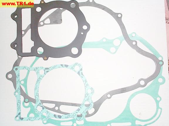
Here are the remaining gaskets from our overhaul kit.
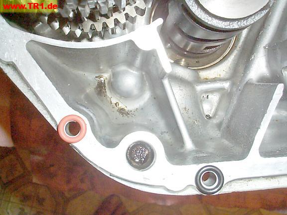
It’s important to choose the correct size of O-ring.
Two sizes of O-rings in our gasket set are almost the same size.
The red O-ring on the left is a bit thicker, and has a smaller inside diameter than the black O-ring on the right.
The two case-half holes are used for a visual reference only: the holes are the same size, unlike the O-rings.
The round case hole between the two O-rings is for a locating dowel.
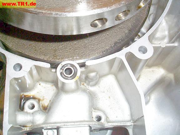
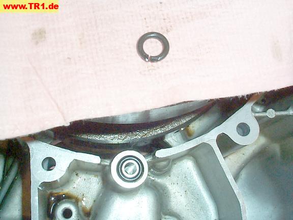
This is the only broken O-ring we found.
It surrounds the oil passage from the pump to the filter.
Filtered oil is sent to the crankshaft big-end rods and the cylinder head camshafts through this case-half-to-case-half O-ring.
The new and old O-rings with the oil collar.
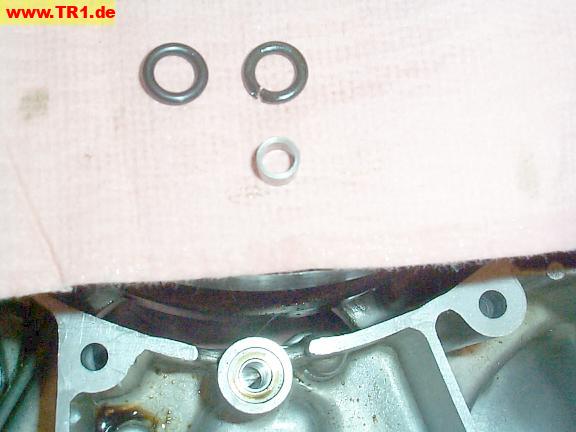
The new O-ring and collar are installed.
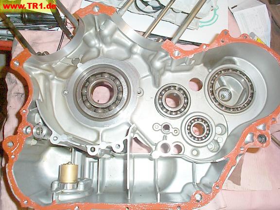
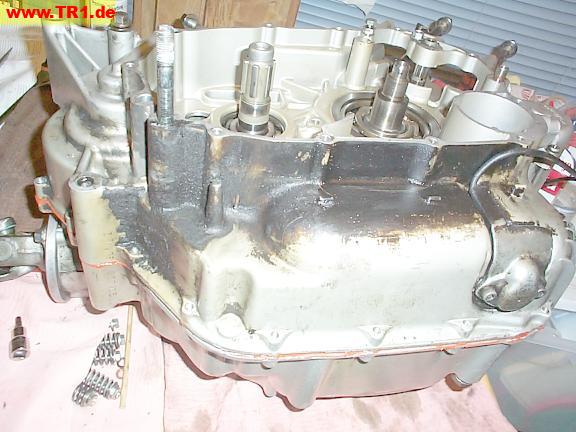
The right-hand case half, with bearings, only weighs 20 pounds (9 kg).
From left to right: bearings for the crankshaft, transmission mainshaft, drive axle, and middle gear bearing. The damper shaft needle bearing is at the center of the middle gear bearing.
The copper-colored cylinder at the bottom front is the oil level sensor.
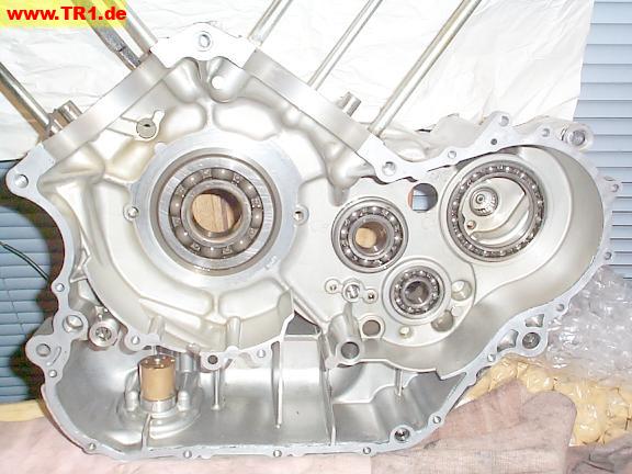
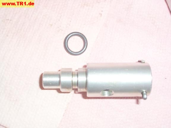
The round thing with the cotter pin through it is the oil pressure relief valve.
This valve releases oil inside the case if the oil pressure becomes too high. As oil tends to be thicker when it’s colder, and isn’t generally compressable, the valve relieves excess oil pressure back into the oil sump before something bad happens.
The top of the oil level sensor is just visible (bottom).
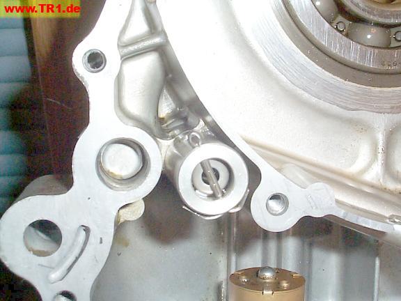
The oil pressure relief valve simply pulls out.
An obstruction in the opposite case half prevents this part from coming out after the case halves are joined.

The oil pressure relief valve.
The assembly is hollow. Inside the assembly, there’s a little spring (near the cotter pin) pushing a plunger towards the inlet (top). If the oil pressure pushes the plunger hard enough to overcome the spring pressure, the plunger uncovers a hole in the side of the assembly that allows the oil to escape back into the crankcase.
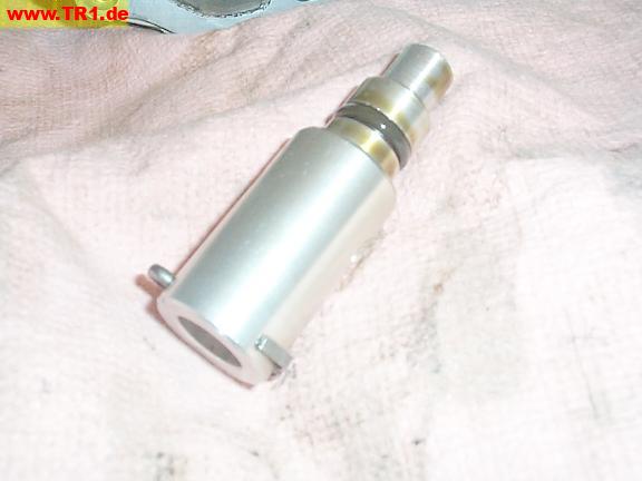
The oil pressure relief valve and its O-ring.
Our overhaul kit lacks this O-ring. Pah! As this O-ring seems to be in fine shape, we chose to reuse it. (This is not generally recommended.)
In hindsight, we should have verified that the piston could be moved by a small screwdriver inserted through the oil inlet hole, or just disassembled it. We focused on the near-term goal of getting the engine together. We’ll strive to make different errors next time. ;-)
The relief hole is visible to the left of the cotter pin.
The left case half.
We’re ready to put the case halves together.
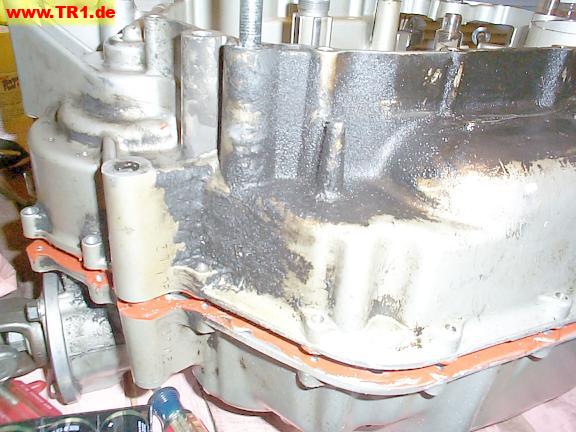
Both case mating surfaces have been scraped, cleaned with solvent, and fingerpainted with high-temperature instant gasket.
It’s preferable to apply as little instant gasket as necessary to avoid having strips of instant gasket eventually collecting around the oil pickup screen, yet apply enough to seal any potential oil seepage. We strived to just hide the aluminum, but still got a bit more gasket material squeezed out than we would have preferred.
If we had wanted to trade slightly reduced seal effectiveness for an easier separation in the future, or wanted to reuse this seal in the future, we would have applied instant gasket to only one surface, and coated the other surface with a thin sheen of oil. If the surfaces had not been machined to close tolerances, or if we had wanted a thicker, springier seal, we would have applied a thicker layer of instant gasket, and let it mostly harden before torqueing.
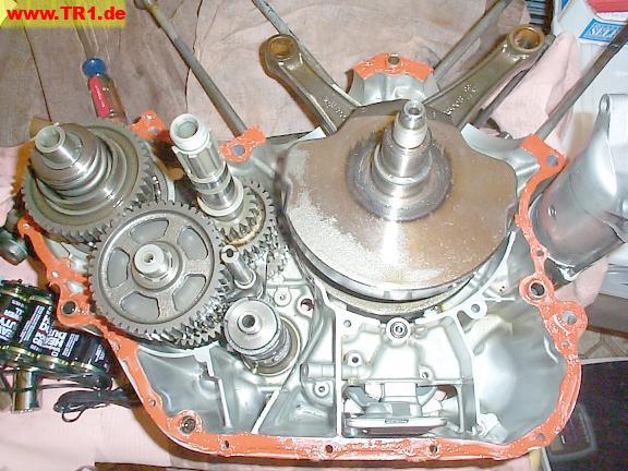
The right case half.
This case half weighs only 20 pounds (9 kg). It’s sweatless to position over its mate.
Almost together.. for about 5 minutes. Gee.
The case half seems to be hanging up on the middle gear assembly.
Bummer. We’ll try wiggling it in various ways.
Together at last.
The case halves clunked together after we widened the the gap near the starter at the front of the engine, the farthest point from the place it appeared to hang.
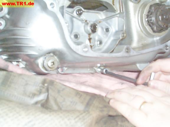
This is the half-moon shifter fork shaft and its retaining bar in the right case half.
The service manual suggested removing the retaining bar when joining the case halves, then applying thread locking compound to the screws before reinstallation of the bar. Being efficient, we simply chose to align the shaft before joining the halves, and check it afterwards. No problem.

We’re installing the 19 case-half bolts, in order, and just finger-tight.
There are 19 case-half bolts: three of these are larger-diameter bolts around the two cylinder holes; of the remaining 16 smaller-diameter bolts, three are inside the left case-half.
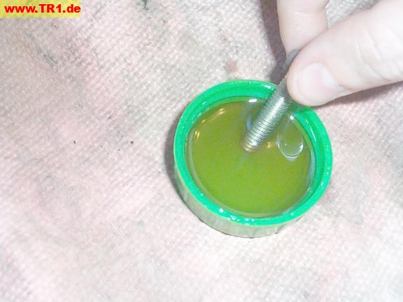
Every bolt gets a bit of oil before it’s inserted. The occasional grubby bolt first gets a light wire bristling (in the direction of the threads) followed by a cleaning with a shop rag.
If a bolt hole feels a bit grubby, we’ll carefully thread a slightly longer bolt a bit past where the correct bolt’s threads would stop at, just to displace any built-up gunk.
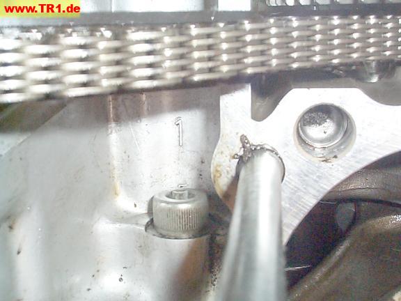
Near each of the 19 bolt holes is cast a number that indicates the recommended tightening order.
Hmmm. Too bad the case was cast with two ‘1’s and no ‘5′.
This numeral ‘1′ is between the bolt (not the head stud to its right) near the rear cylinder, below the cam chain.
This numeral ‘1′ is to the left of its bolt, under the rear left motor mount.

No problem: we have the Genuine Yamaha Service Manual, published by no less an authority than the Yamaha Motor Corporation, USA. This manual contains a pictorial of the recommended bolt tightening sequence using
numbers from 1 through 19, inclusive – unlike the case casting. That’s odd: the manual contradicts the cast numerals on the tightening sequence of two other bolts.
Hmmm. 2nd printing, May, 1985; first edition, December 1983; Yamaha Motor Corporation, USA. I wouldn’t expect such a commonly-referenced pictorial to have any errors that survive undetected for more than a year. They probably meant it – but this still seems odd.
But wait, there’s more! One pictorial might have been good enough for other shop manuals, but this manual has a second pictorial, just one turn-of-the-page later. It’s even identical to the previous pictorial – usually a good sign.
But wait! There’s still more! We find yet a third pictorial in the appendix. Unfortunately, this pictorial disagrees with the previous two. This is not a good thing to discover while the instant gasket is solidifying. ARGH!
Well, the latest pictorial matches all the cast-in numbers on the case halves that aren’t obviously in error, and seems to make a more orderly pattern, so we’ll pick this one. So: bolt number one shall be under the motor mount, bolt number 5 shall be by the rear cylinder, all the other cast numbers appear correct, and we have yet another story to tell.
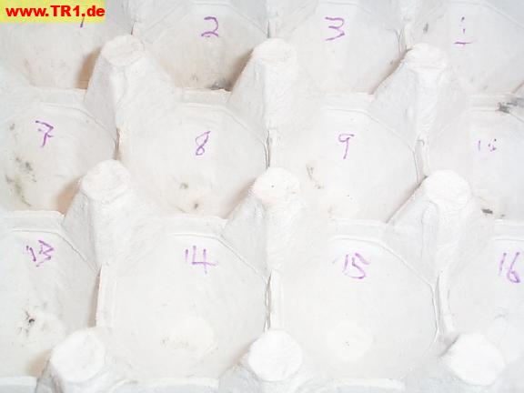
The numbers are also useful for keeping track of which bolt goes in which hole, particularly in conjunction with an egg carton with matching numbers in each compartment.

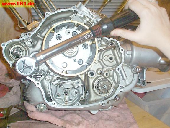
The three large (10 mm [thread diameter]) bolts surrounding the cylinders get torqued to 39 Nm (28 foot-pounds).
Click-type torque wrenches are cool.

Three of the case-half bolts are inside the left sidecase.
The 16 small (6 mm thread diameter) bolts get torqued to 10 Nm (7.2 foot-pounds).
The larger torque wrench can’t measure torque this low, so we’ve swapped wrenches.
The oil pump remains unbolted to get at case bolt # 8 (right).
The red O-rings surround the two oil passages to and from the pump. The dowel below the left O-ring provides physical rigidity between the pump and case.
We’ve replaced one of the two O-rings.
The new O-ring (upper left) is and toroid-shaped and dull; the old O-ring (lower-right) is old, sorta flat, and shiny.
Both O-rings are pliable, not brittle.
Our engine overhaul gasket set only included two orange O-rings, but we’ve found five old O-rings of this size so far. We’ll be paying a visit to the friendly Yamaha st^H^Hdealership again later.

The case halves are torqued together.
This is the right side: we’ll add the primary gear, clutch and timing gear to this side, next.
The wire hanging down (bottom left) goes to the oil level sensor.
