Now, we’ll time the front (#2 cylinder) timing gears.
We’ve already timed the rear (#1 cylinder) gears.
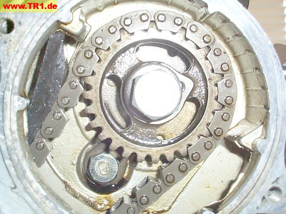
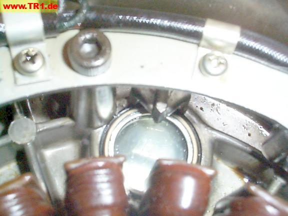
The front cylinder’s timing gears live behind the right-hand crankcase cover.

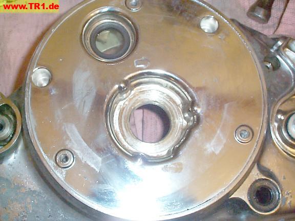
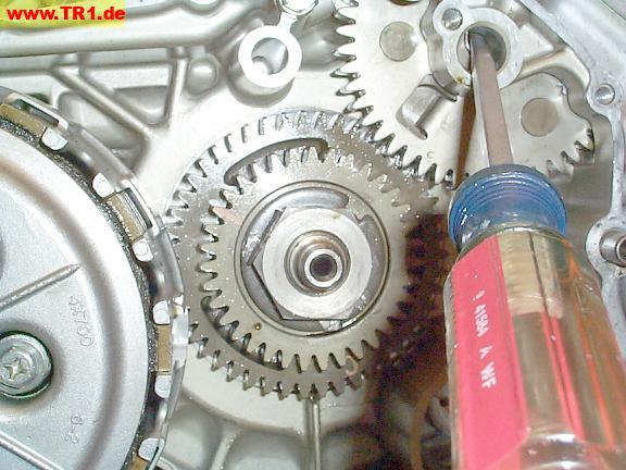
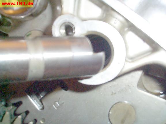
We can now remove the driven gear’s shaft and easily lift the driven gear, along with the pinned anti-lash gear, up and away from the crankshaft gear.
We’ll keep the gears separated by the weight of this screwdriver.
We can now rotate the crankshaft, along with the #1 (rear) camshaft, without moving the front timing gear.
We’ll use the timing window to more accurately set the crankshaft to its timing mark.
We have to remove the Yamaha emblem to see the timing window: it’s retained by three screws.
These screws wouldn’t budge with a screwdriver, so we used an impact wrench.
The impact wrench body is first twisted slightly (counter-clockwise for loosening) against the tool’s internal spring pressure. The screw loosens when the end of the impact wrench is hit with a hammer.
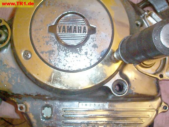
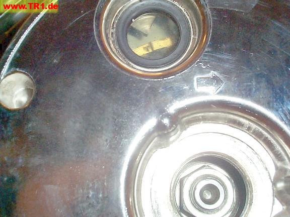
We can now see the timing window (at the upper left).
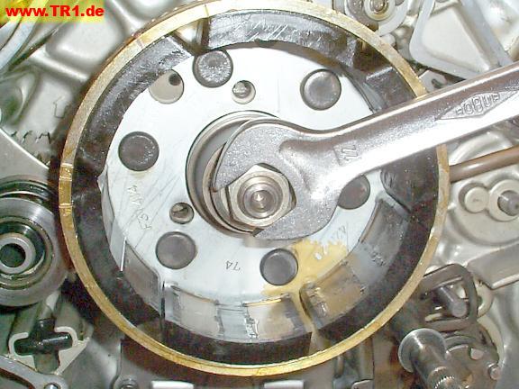
The round crankshaft-end cover in the middle of the sidecover provides access to the crankshaft bolt.
This cover bears a striking resemblance to a Honda 305 valve tappet cover.
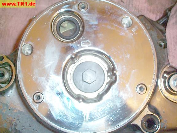
The timing pointer is visible behind the plastic timing window.
We’ll want to watch the timing window while rotating the crankshaft, so we’ve also removed the crankshaft-end access cover.
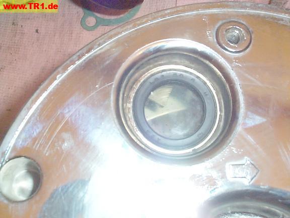
The arrow above the crankshaft access hole shows the normal direction of rotation of the crankshaft (this is the left side – it rotates clockwise).
Another way of remembering which way the crankshaft spins: if the bottom of the spinning crankshaft could touch the ground, the crankshaft would move towards the *rear* of the motorcycle.
Also, the camshafts spin in the *opposite* direction of the crankshaft.
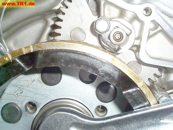
Here’s the inside of the left sidecase cover.
The timing window resides between the two crankshaft position sensors (under the curved metal bracket) and the alternator stator coils.
The crankshaft position sensors sense the holes drilled in the side of the alternator rotor as the rotor turns, and command the ignition modules to generate a spark.
Because there is no camshaft position sensor, each coil provides a spark just before TDC (top dead center) at both the end of the compression and the exhaust strokes, but only the former is useful.
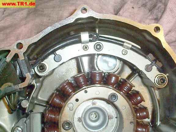
The timing pointer resides at the very top of the window.
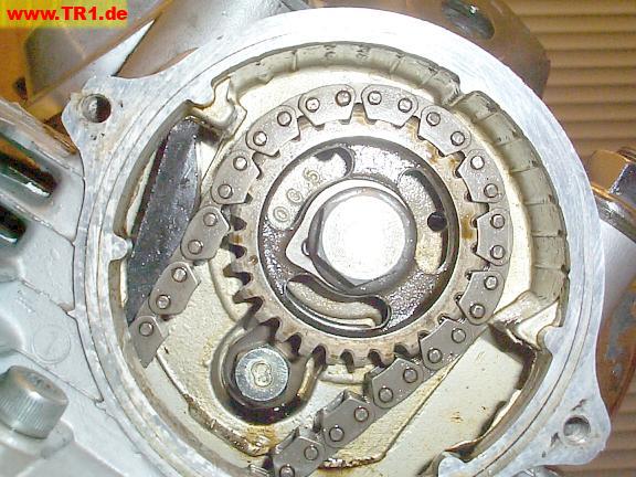
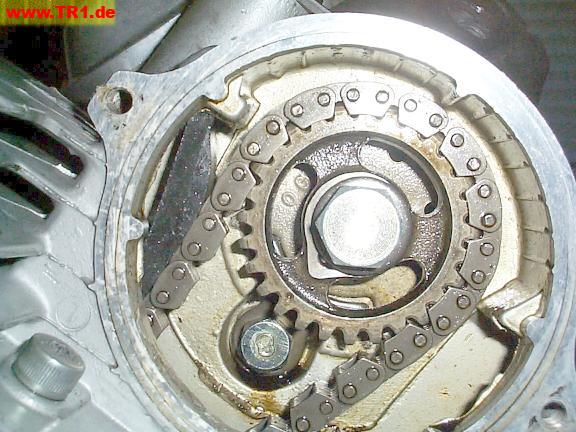
We’ll use the #1 cylinder’s timing to time the #2 cylinder. This is the #1 cylinder’s camshaft sprocket, at the engine’s left rear.
We rotate the camshaft in its normal direction of rotation, counter-clockwise, by moving the bolt on the left-hand end of the crankshaft clockwise.
The timing dot on the sprocket is within a half-tooth of its case timing mark.
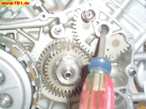
We’ve temporarily installed the left engine cover so we can more accurately set the crankshaft timing.
The marked edge of the alternator rotor is visible through the window.
While looking through the timing mark window (on the left side), we rotated the crankshaft to the ‘T’ (timing) mark.
There are only three timing marks that we might view through this window:
We can grok what’s going on a lot easier by just making our own pointer out of a paper clip.
As the alternator/flywheel is turned clockwise (as viewed from this side):
We’re (still) at the ‘T’ (#1 cyl TDC) mark.
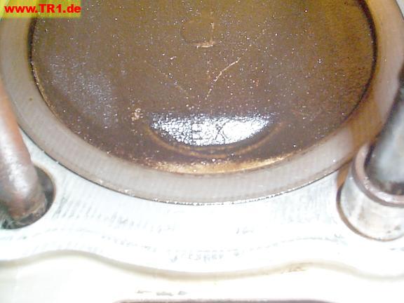
This is the #2 (front) piston.
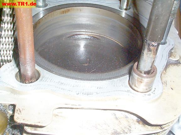
We’ve continued to turn the crankshaft until the front piston (shown) reached BDC (bottom dead center).
(The front piston is still at BDC.)
This rear camshaft is at about 52 cam degrees, more than halfway through its power stroke. (The camshaft turns counterclockwise.)
(The front piston is still at BDC.)
We can also verify that the front piston is at BDC because the crankshaft timing dot is furthest away from the front timing gear.
The crankshaft is turned (clockwise) to the #2 (front) cylinder’s timing mark (the single line near the top of this image).
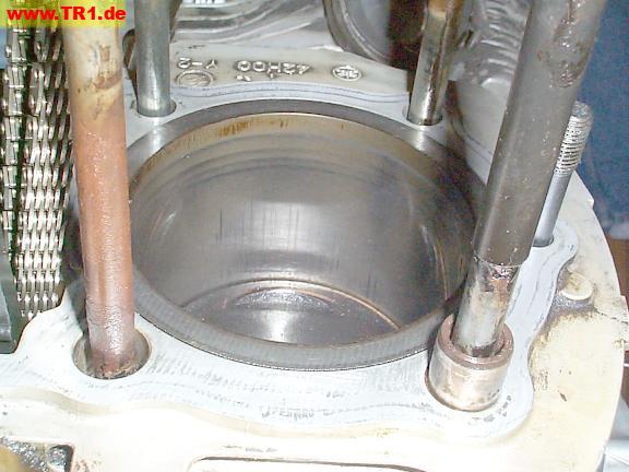
The front piston is now at TDC.
(Unfortunately, the timing mark pointer is not quite visible. Darn.)
The front piston is at TDC (shown).
(The front piston is still at TDC.)
This rear camshaft is at about 142 cam degrees, more than halfway through its exhaust stroke. (This critter turns counter-clockwise.)
The front piston is at TDC, at the start of its power stroke, the timing window shows a single line (the front cyl timing mark). and the front camshaft should now be set at its timing mark.
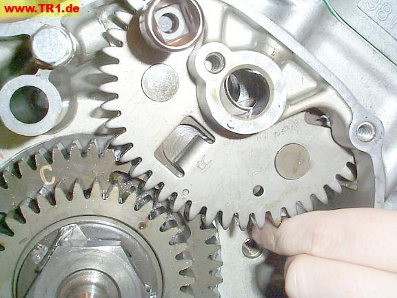
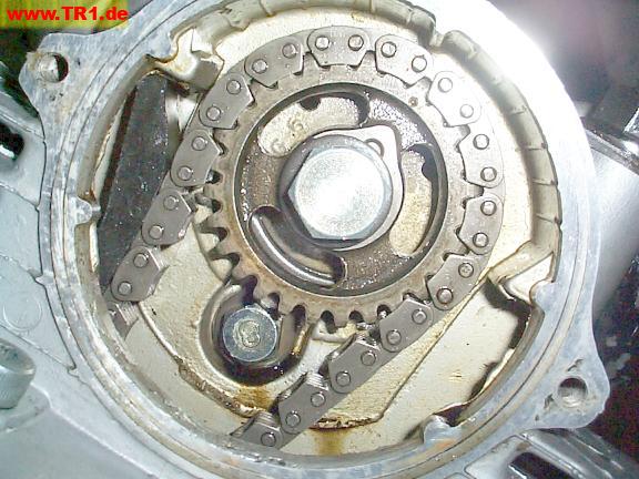
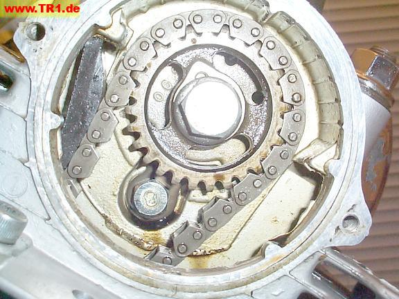
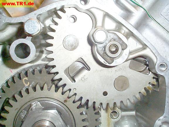
The front timing gears’ dots are now aligned,and we’ve allowed the front driven (upper) gear to drop down, meshing with its driving (lower) gear.
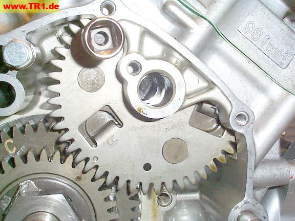
The front timing gear shaft is reinserted – with its oil catcher facing up – so oil will lubricate the driven gear.
The front timing gear shaft retainer is installed and torqued.
We’re done timing the front timing gear.
Just for fun, we’ll turn the crankshaft some more while noting the rear camshaft, front piston, and crankshaft timing marks.
When we’re done taking pictures, we’ll turn the crankshaft backwards to where it is now, so the timing dots again line up.
We’ve turned the crankshaft until the timing window again shows ‘T’ (the rear piston is again at TDC), but this time the rear camshaft is at 180 cam degrees (shown), so the rear piston is now at the start of its intake stroke, not its power stroke.
This rear camshaft is now at about 232 cam degrees (shown), more than halfway into its intake stroke.
The front piston is at BDC, the start of its exhaust stroke.
The timing window shows a single line (#2 piston TDC).
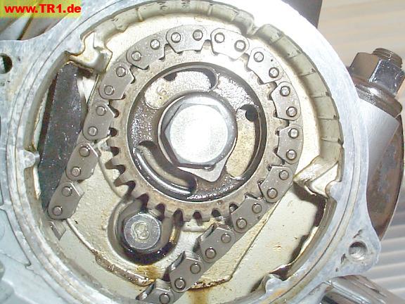
This rear camshaft is pictured at about 322 cam degrees, more than halfway into its compression stroke.
The front piston is at TDC, the start of its intake stroke.