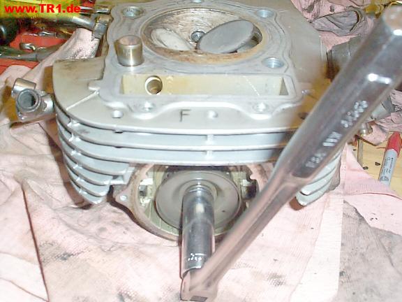
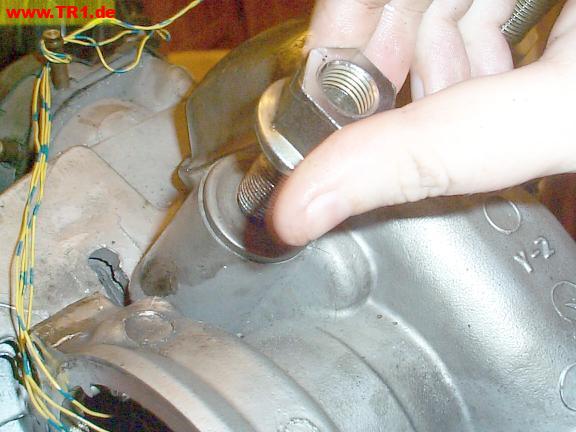
We did a quick check of the valves without removing them from the head.
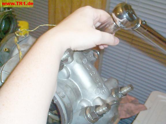
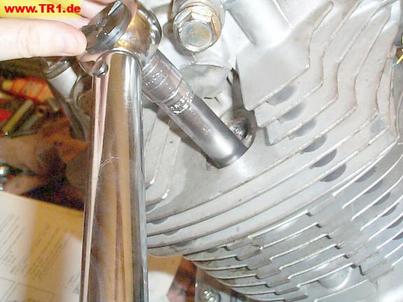
We used a breaker bar on a deep socket to rotate the camshaft bolt to examine the seating surfaces.
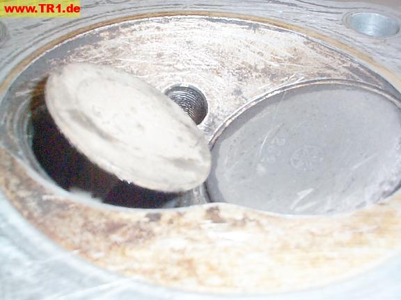
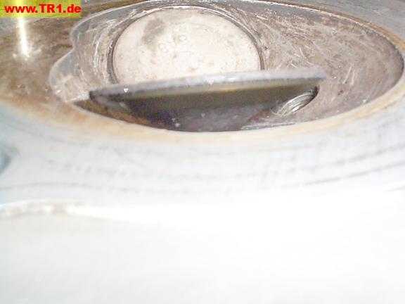
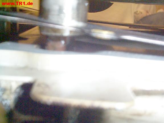
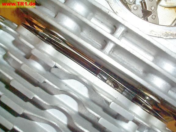
The exhaust valve (left) opens as we rotate the camshaft nut.
The diameter of each valve is just a bit larger in diameter than the circular opening it covers when it’s closed. The head and valve have a similar bevel. We’re looking for a nice smooth, uniform ring where the head and valve seat together when closed.
A moderate amount of torque is required to overcome the valve spring pressure.
Exhaust valves tend to run hotter, and take on a lighter appearance, than the cooler-running intake valves.
Exhaust valves are typically smaller than intake valves because the intake gas [the air/fuel mixture, not just gasoline) is sucked into the cylinder at a much lower gas pressure than the exhaust gas is expelled.
(Disclaimer: I am not an automotive engineer.)
The exhaust valve, from the side.
The valve’s sealing surface appears as a darker, beveled ring just below the top of the valve.
More efficient engines utilize two intake and exhaust valves per cylinder
to make it easier for the cylinders to ‘breathe’.
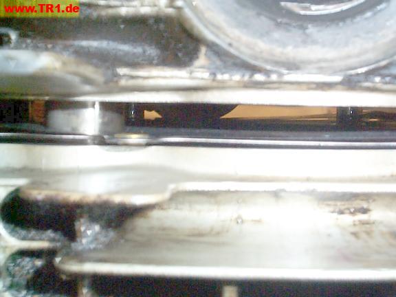
As we continue rotating the cam, the breaker bar is being pulled from our hands as the exhaust valve spring closes the valve.
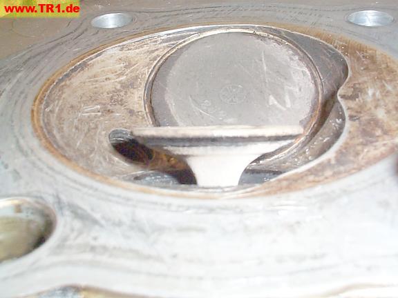
The intake valve, from the side.
The valve’s seating surface is visible as a brighter, beveled ring just under the top of the valve.
We’ve cleaned the front cylinder’s mating surface where the head gasket and head will sit.
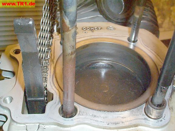
A new head gasket has been placed over the studs, cam chain and guides.
We’ll thread the cam chain into the head with this wire.
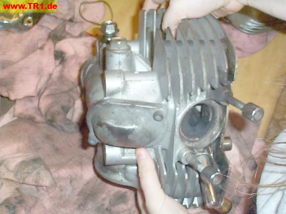
This is the front head. The exhaust port is to the right.
The camshafts in the two heads differ: according to the manual, the rear and front camshafts should be marked ‘1′ and ‘2′, respectively. Somewhere.
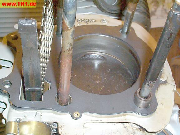
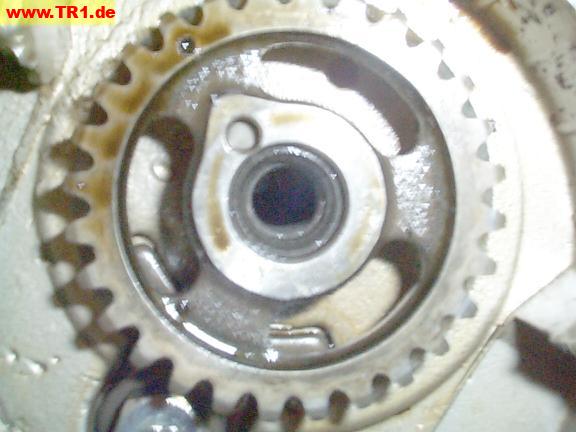
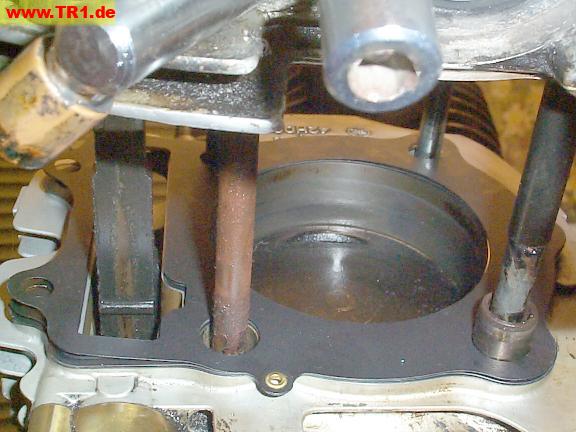
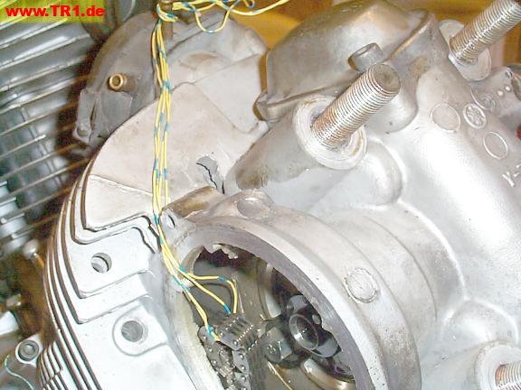
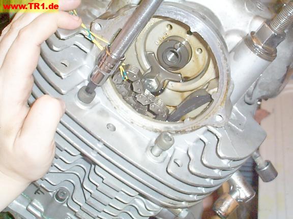
We’ve removed the bolt, washer and oil slinger so we can see the cam sprocket in the head.
The cam sprocket turns with a finger-touch over the section of its travel where both valves remain closed.
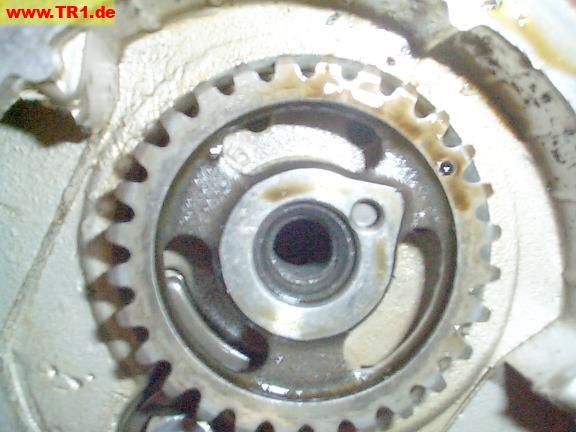
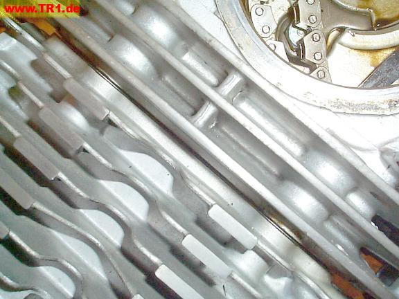
We’ve turned the camshaft counterclockwise as far as we can by hand.
As the camshaft is normally rotating clockwise [as viewed here), the intake valve has just closed, and the piston is beginning to compress the air/fuel mixture in the cylinder.
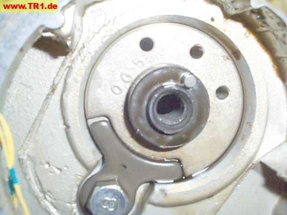
We’ve turned the camshaft clockwise as far as we can by hand; the exhaust valve would begin to open at this point.
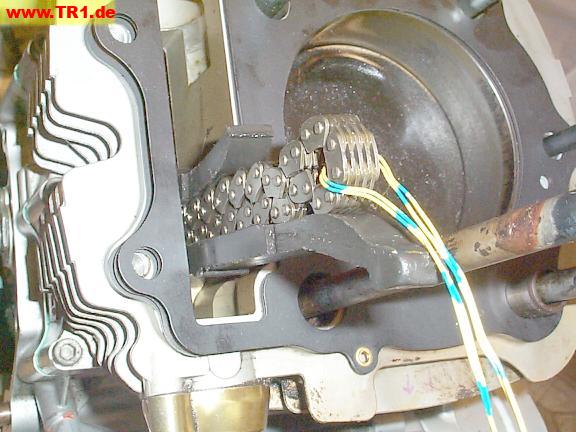
We’ve removed the sprocket from the end of the camshaft so we have enough room to pull the cam chain up by its wire.
The front cam chain sprocket, oil slinger, washer and bolt.

We’re lowering the front head onto the head gasket and cylinder.
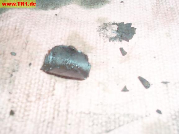
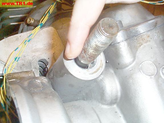
Some old, yucky plastic anti-noise head stud coating was apparently left behind in the head. The remains jammed between the studs and the head passages, and preventing the studs from being inserted all the way through the head.
We had to clean the head stud passages with a screwdriver before installing the head all the way.
Because one of the two dowels remained attached to the head, we had to reposition the head gasket onto this dowel manually as the head got close to the cylinder.
Both dowels are now touching both the head and cylinder.
The head is almost seated.
The head gasket is actually a three-part fiber/metal/fiber sandwich.
We lightly hammered on a piece of wood held against the top of the head to seat the head.
The fins tend to be brittle, so we avoided applying force around the outer edges of the top fin.
The head is effectively seated.
We’ll lubricate the threads on each stud with a little oil.
Next, we’ve added oiled washers.
Finally, we threaded the stud nuts up to their washers by hand.
We’re ready to torque the head.
First, the four head stud nuts are torqued in a criss-cross pattern.
Next, we oiled the underside of the cap nut and its threads before torqueing it.
Finally, we torqued the two head bolts.
The front head is finally torqued onto the engine.
Next, we’ll add the camshaft sprocket and time the front camshaft.

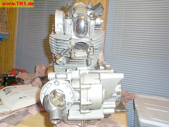
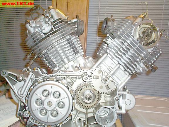
This is the right-side view.
The clutch lives on this side.
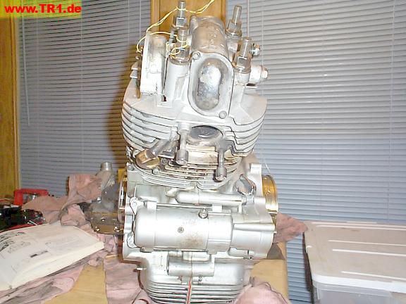
The front view.
The starter lives below the front exhaust port.
The alternator [image right) protrudes farther than the clutch (image left).
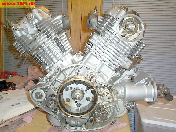
The left side view.
The alternator, gearshift and starter gears live on this side.
The rear view.
The U-joint is at the rear left.
The free end of the U-joint will mate with the driveshaft when the engine is reinstalled in the frame.