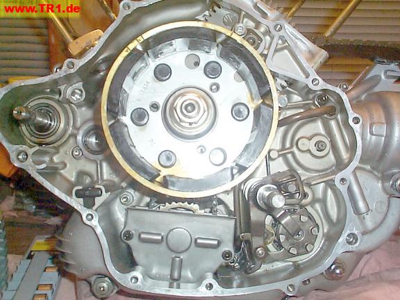
Here’s the left-hand sidecase.
We’ll want to change some O-rings, secure the oil pump, and add the shifter and starter stuff.
The alternator/flywheel, shifter drum and left timing gear have remained attached throughout this saga.
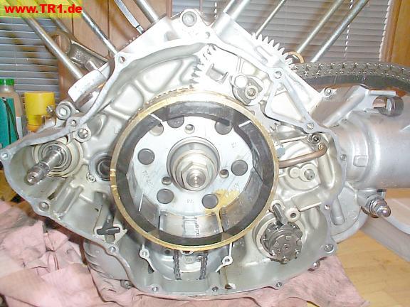
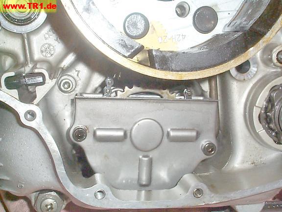
We’ve replaced the two O-rings that feed oil from the oil pump.
The oil pump mounting dowel, three mounting threads and case-half bolt # 8 (upper right) are visible.
We moved the oil pump to the extreme right to get at these O-rings.
Because we haven’t removed the alternator rotor or unscrewed the oil pump halves, there’s not quite enough room to extract the oil pump from under the alternator.
We determined that the oil pump (and copper pipe) O-rings use the smaller-inside-diameter (and thicker torus) size.
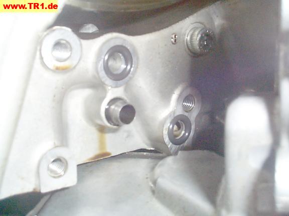
The oil pump is fastened to the case by three hex bolts.
The phillips screw only holds the oil pump halves together, but doesn’t attach the oil pump to the case.
Case-half bolt # 8 is almost completely hidden by the oil pump.

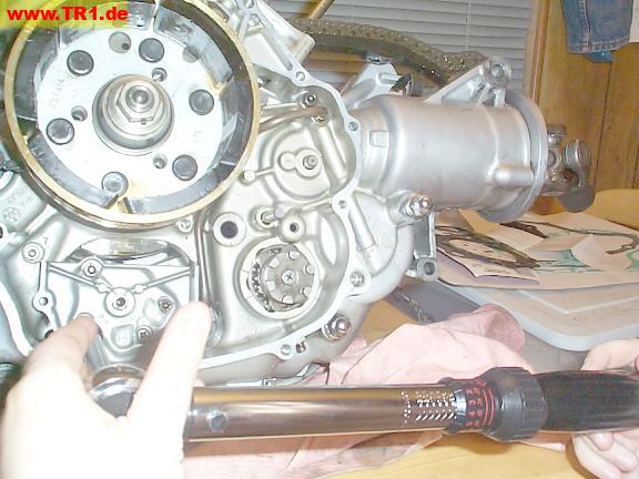
We’re torquing the remaining oil pump mounting bolt.
The oil pump driven sprocket is keyed to the oil pump shaft.

Hmmm. The chain has enough slack to slip off. Something’s not correct.

Aha! The oil pump chain had slipped off its crankshaft sprocket.
The chain is resting between the crankshaft bearing (left) and its sprocket (right).
The starter motor shaft is at the bottom left.

It’s easy to wiggle the chain back on its sprocket.
This is where the oil chain *should* be.
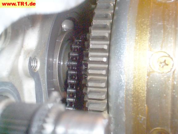
Now that the chain is on both sprockets, we’ll add the oil pump sprocket bolt and torque it.
While torqueing this nut, we held the alternator to prevent the sprocket from rotating. The cam chains would also tend to bunch up and jam if the alternator were allowed to rotate.
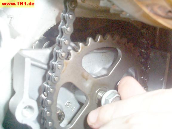
The oil pump chain cover prevents the oil pump chain from sucking oil away from the oil pickup and adding air bubbles to the oil like a mini-blender.
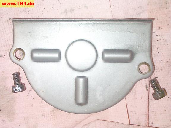
We’ll torque both oil pump sprocket cover bolts.
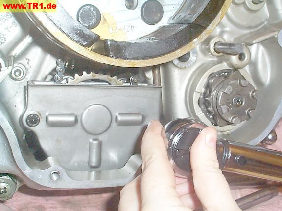
We’re done with the oil pump.
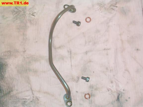
This metal oil pipe easily lifts out after removing its two hex bolts.
We’ll replace these O-rings while we’re in the neighborhood.
These O-rings are the same size as those used with the oil pump.
The top end of the oil pipe ends just above the clutch pushrod.
It appears that one of the internal passages would carry oil towards one of the middle gear bearings (lower right of image).

The bottom end of the middle gear oil pipe is torqued to the case to the right of the oil pump.
It appears that some oil flowing through this pipe will feed the middle gear assembly (right).
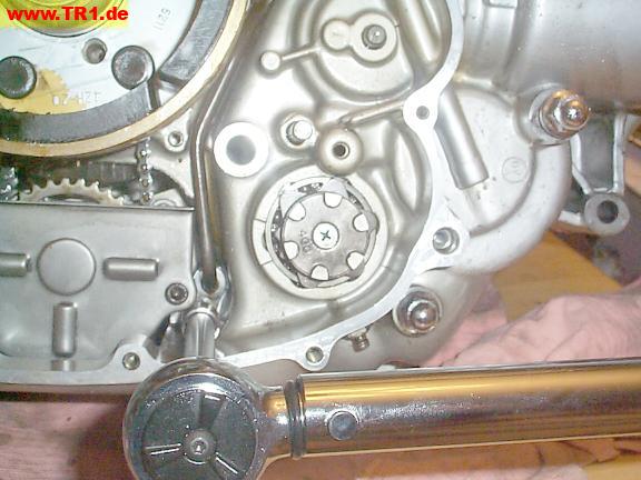
Next, we’ll install the shifter assembly.
The detent roller (lower left) and one of the two shifter pawls (top) are visible.
The splined end of the shifter shaft (bottom right) protrudes outside the cover, attaching to the shift pedal linkage.
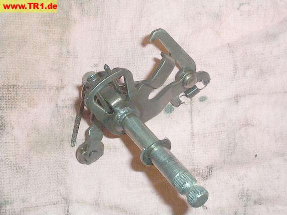
A side view of the (left to right) shifter drum detents, pins, and slots, viewed from the front of the engine.
The detents hold the drum in the current gear position.
The two smaller detents separate 1st speed (above) from 2nd speed (below).
The pins pull the drum clockwise or push the drum counterclockwise.
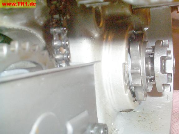
One end of the shifter shaft fits in its bushing between the alternator and drum.
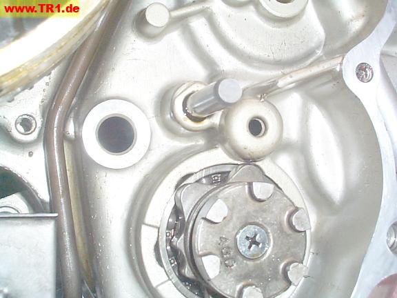
It’s necessary to hold the shifter pawl open during installation to allow it to pass behind the front of the shifter drum.
The shifter drum detent happens to be at neutral, between 1st and 2nd speeds.
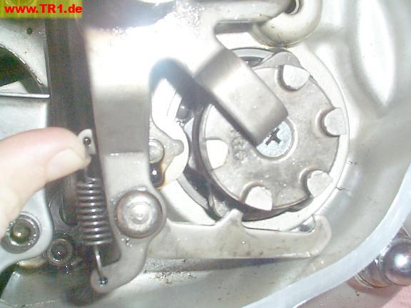
The shifter shaft (top left) will protrude outside the side cover.
The two heavy springs on either side of the smaller shaft (to the right of the larger shifter shaft) hold the shifter in the middle of its travel to allow either up or down shifting. The smaller shaft also limits the maximum shifter shaft rotation to one gear change at a time.
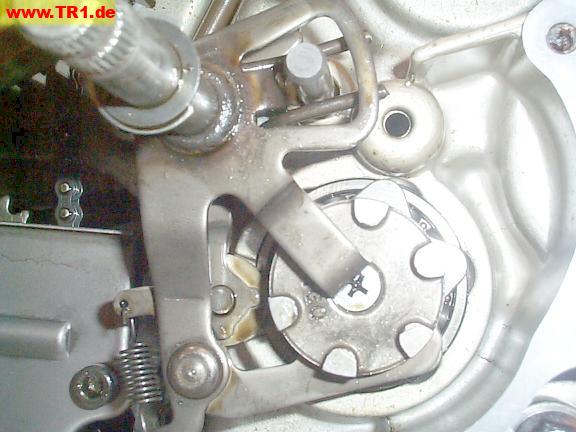
We’ll use a screwdriver to shove the top end of the detent roller spring into position against its post.
The lower end of this spring holds the detent roller between two bumps on the side of the shifter drum, holding the shifter drum at the current gear position.

The small spring (bottom left) holds the shifter pawl arm lightly against the bottom pins of the shifter drum.
The pawls at the bottom push or pull the pins (not visible) to rotate the shifter drum to an adjacent gear position.
The flat metal piece (obscuring the drum screw) normally slides between the slots on the disc.
The shifter detente roller is holding the drum in the neutral gear position.
Cool.
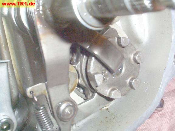
The shifter assembly, viewed from the front of the engine .
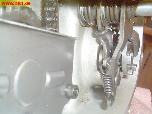
The shifter assembly, viewed from the rear.
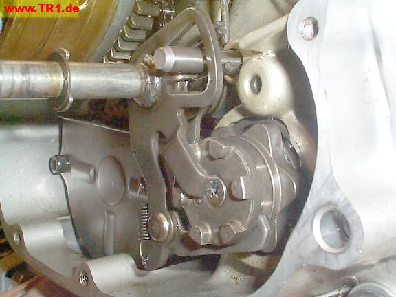
The oil pump and shifter assembly are installed.
Only the starter gears remain to be added to this side.
