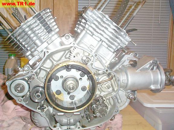
The left side.
It’s (past) time to time the rear cylinder. If we had though ahead, we would have timed the rear timing gears before installing its cylinder, as it’s easier to mesh the timing gears without the cylinder in the way. However, it would be even more work to remove and replace the cylinder just to time it.
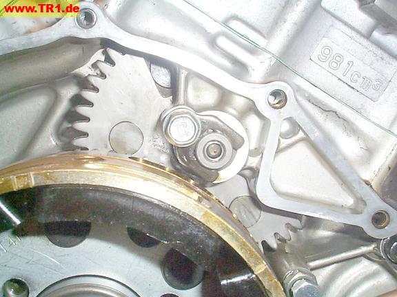
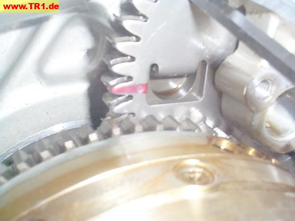
The driven timing gear for the rear cylinder is visible between the alternator/flywheel and cylinder base.
The driving timing gear lives on the crankshaft, behind the alternator/flywheel, and isn’t visible.
The driven timing gear is directly connected to a sprocket (not visible; behind the timing gear) that pulls the lower end of a cam chain; the upper end of the cam chain (in the cylinder head) pulls a sprocket on the camshaft.
Because there are many more timing gear teeth than timing gear sprockets, we set the valve timing (rotational degree offset) between the crankshaft and camshaft partly by choosing at what point to mesh the camshaft driven gear with the timing gear. We can also more coarsely adjust the timing by moving the chain by one sprocket.
The timing gear mark is marginally visible (at the base of the second tooth from the bottom) in this image.
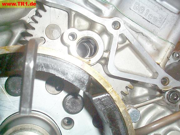
We’ve placed a hex wrench in the timing gear anti-lash alignment hole, then removed the timing gear shaft so we can reposition the timing gear by hand. The tool keeps the timing gear and anti-lash gear [almost] aligned, allowing us to (more
easily) mesh this assembly with the driving gear on the crankshaft (not visible; it’s below and in back of the ring gear).
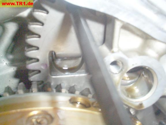
We’ve drawn a purple felt-tip-marker line across the timing dot for increased visibility.
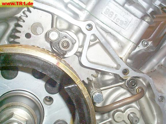
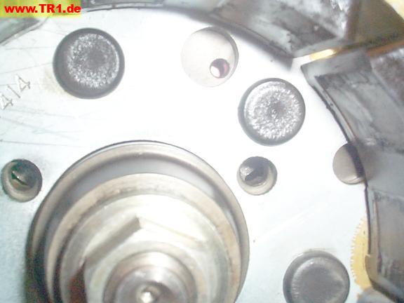
The timing hole is the tiny hole within the circular cutout at 1 o’clock from the crankshaft. The crankshaft is turned so the hole is nearest (pointing directly towards) the timing gear shaft.
When the timing hole is pointed towards the timing gear shaft, we should be able to see the timing mark by looking through the timing hole. A flashlight is quite useful.
The tool in the anti-lash hole is prevents us from moving the timing gear mark to the timing hole. We have to remove the tool. That’s odd.
The Genuine Yamaha Service Manual makes no mention of this interesting procedural detail. There are clues, though: the manual lists step 5 as gear installation, and step 6 as alignment of the ‘timing gear hole with flyweel timing hole’ (sic).. and step 6 as shaft installation (yes, there are two ’step 6’s here). Ah, well. Lowered expectations tend to result in less disappointment.
The process of removing the tool is performed by pushing the gear down from the top of the cylinder with a really-long screwdriver, removing the tool, and removing the screwdriver, allowing the gears to unmesh. It seems that we can’t time
this gear while the anti-lash gear is locked to the timing gear.
We’ve repositioned the timing gear by hand so the timing mark is visible through the timing hole.
Though the anti-lash gear is now preventing the timing gear from moving down far enough to mesh, the timing
gear is now at exactly the proper height to see the timing gear mark through the hole.
We will simultaneously rotate the alternator and timing gear back far enough to be able to access the anti-lash alignment hole, mesh the gears, add the shaft, and rotate it forwards again to verify the timing.
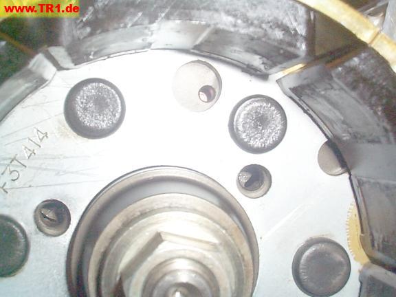
The timing appers correct. A slight scribe mark made through the timing hole (not visible in this image) was just perceptible above the timing mark (on the timing gear itself, through the cutout in the anti-lash gear) when the timing gear was subsequently rotated clockwise sufficiently to view.
The shaft retainer has been added and torqued.
We’re done timing this gear.