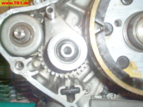
The infamous Virago starter stuff lives here, at the front end of the left sidecase.
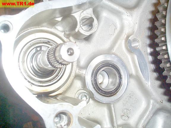
The magnet (bottom middle) lives on the end of the starter oil catcher, under the starter gears..
Both the starter shaft and large ring gear rotate clockwise to start the engine.

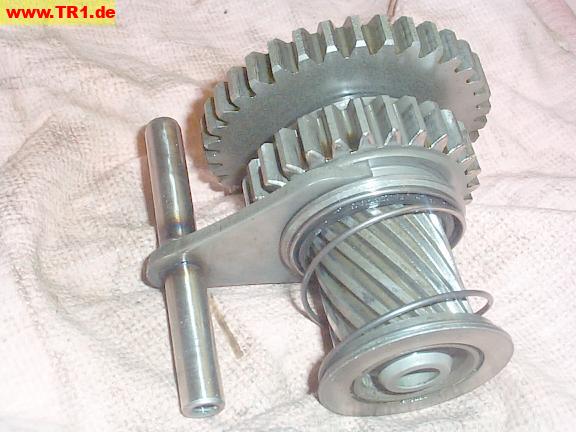
The starter gears.
From left to right: washer, gear ‘A’, gear ‘B’, spring, and the spiral gear.
Gear ‘A’ (larger) is normally fixed to the end of the spiral gear by splines.
Gear ‘B’ (smaller) is moved along the spiral gear by its fork.
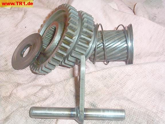
The starter gear shaft runs through all these parts.
The splines that fix gear ‘A’ onto the end of the spiral shaft are visible.
The shifter fork slides gear ‘B’ along the spiral shaft.
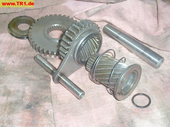
These parts rotate counterclockwise to start the engine.
The large gear ‘A’ (top) is always meshed with the starter clutch.
The smaller sliding gear ‘B’ is normally held disengaged from the flywheel/alternator’s ring gear by its spring and fork.
When the starter solenoid is energized (by the starter button), the solenoid pulls the fork and its sliding gear ‘B’ towards the flywheel/alternator ring gear, compressing the spring. The solenoid also applys power to the starter motor which begins moving these gears counterclockwise.
I suspect the solenoid must first pull the sliding gear close to the ring gear *before* the solenoid can begin applying power to the starter motor – so the sliding gear spins slowly (if at all) as it touches the ring gear – but I don’t know. (Gears mesh easier with a slower speed difference.)
If the slider gear ‘B’ teeth don’t happen to mesh with the alternator’s ring gear teeth, the gear edges grind, pushed by the shift fork and the spiral gear’s leverage – and the magnet catches some of the filings.
We’ll start the assembly by placing the washer near its position by the bushing.

The starter gear ‘A’ is placed over its washer.
We’ll use a small screwdriver to center both the washer and gear over the bushing, and keep the washer in position with the gear.

The remaining starter shaft parts are installed together.
(The shaft can’t be installed first because the gears would hit the side of the alternator.)
While holding the washer in position, and holding the smaller gear ‘B’ on the splined shaft against spring pressure, we meshed gear ‘A’ splines with the end of the splined shaft, started the shifter fork shaft into its hole, pushed the gear shaft into its bushing (through the washer), and finally added the O-ring onto its shaft to hold everything together.
This took us several tries over several minutes.
While no single step is particularly difficult, this is an excellent finger coordination exercise.
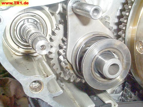
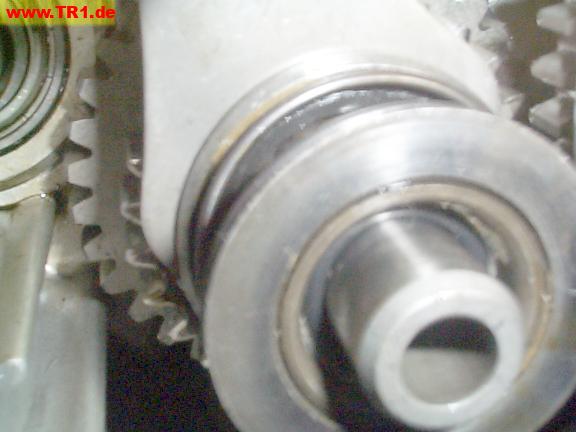
The O-ring around the shaft counteracts the spring’s tendency to disengage the splines between gear ‘A’ and its spiral shaft.
If the O-ring slips, and the splines on the spiral shaft and gear ‘A’ unmesh, the end of the spiral gear will stick out too far, preventing installation of the sidecover.
The starter one-way clutch and circlip fit over the starter motor shaft.
This assembly turns clockwise. The clutch free-wheels if the gear is rotated faster [clockwise] than the splines, but locks when the splines are turned faster (clockwise) than the gear.
This prevents a running engine from [rapidly!] spinning the starter motor.
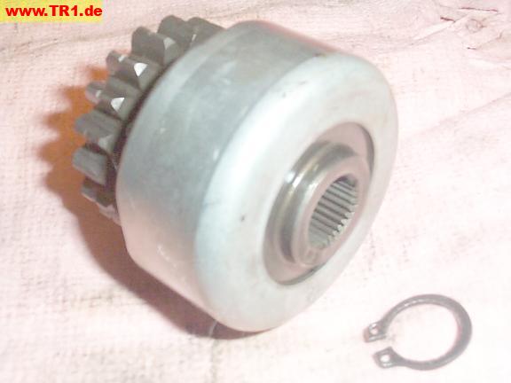
The one-way starter clutch and circlip are installed on the starter motor shaft.
The larger gear ‘A’ is meshed with the starter clutch gear.
The smaller gear ‘B’ is held offset from the ring gear by its spring.
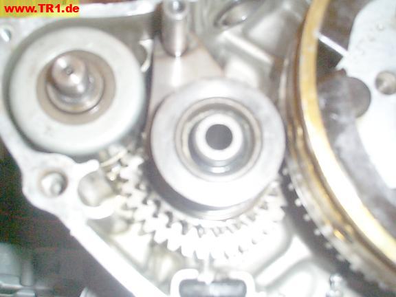
The black rectangular magnet directly under the starter gears (bottom center) catches the metal shavings.
We’re done with the starter.
