![]() Valve Clearance
Valve Clearance
Remove seat, fuel tank (mind fuel and vacuum lines at the fuel valves), air filter unit, and crankcase ventilation pipe. Remove intake and exhaust valve covers. (Silver, on top of the cylinders, 2 screws each) Remove generator cover and crankshaft end cover („1" in fig.11). Align the „T"-mark (for the rear cylinder) on the flywheel with the fixed indicator on the crankcase cover. The indicator is visible through the timing window at the engine housing. When the „T"-mark (fig. 12) is aligned with the indicator the piston is at Top Dead Center (TDC), its upper mark. Valve clearance should be checked and -if necessary- adjusted only in this position of the compression stroke as the rocker arms have a definded free play here. The piston is in the compression stroke when both rocker arms have free play, otherwise during intake/ exhaust stroke. The flywheel features marks as seen in fig. 13. Measure the valve clearance with a feeler gauge as shown in fig. 14. the correct values are: : intake valve: 0,10 mm |
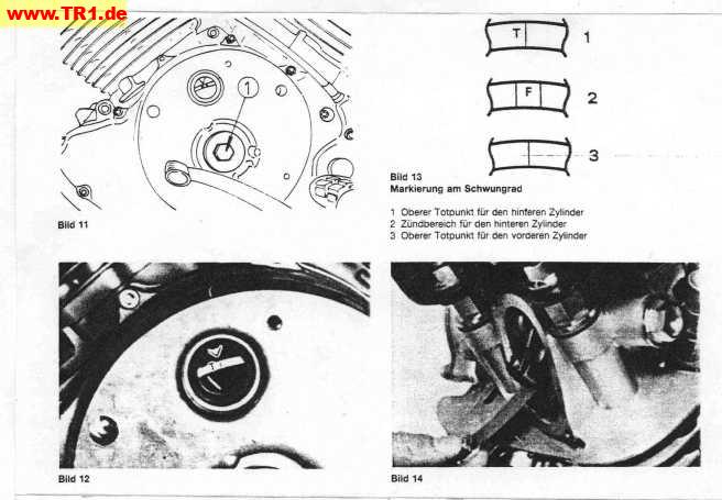 |
Now reposition the crankshaft approx. 285 °clockwise for TDC of the front cylinder. Repeat the afore mentioned stepsto adjust valve clearance of that cylinder as well. Replace covers of the intake and exhaust valves. (When you are happy to have a new spare part hence unaccounted for, oil will spurt out the top when the engine is running meaning you forgot one). Replace generator and crankshaft end timing covers. Replace air filter unit and crankcase ventilation pipe. Make sure the rubber gasket setas in place when mounting the air filter unit. Refit the fuel lines and vacuum lines to the valves of the fuel tank. |
hey, that was fun! now on to ...
Carburetor Adjustment